
| Guarded Heat Flow (ghf-01S) | Request a Quote |
|
The technique
The ghf-01S operates according to the ASTM E1530 Guarded Heat Flow Meter technique [1], for the measurement of the thermal conductivity of solids. According to the technique, the sample is subjected to a steady-state axial temperature gradient. The thermal conductivity of the sample is obtained by measuring the temperature difference across it, and one additional temperature.
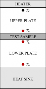
The instrument is composed by the following parts shown in Figure 1.
 |
|
| Figure 1. Schematic diagram. |
The whole assembly in the actual instrument is made out of stainless steel, and in essence the heater is incorporated in the top part of the upper plate, while the heat sink is incorporated in the bottom part of the lower plate. Furthermore, plastic Perspex is employed to insulate the stack.
By applying the Fourier law, it can readily be shown (see ghf-01S Manual) that for any solid sample, the ratio RS (m2 K W-1), equal to the thickness of the sample, d (m), to its thermal conductivity, λ (W m-1 K-1), can be obtained from the temperatures measured
![]()
The above equation is linear in form, and is the working equation of the instrument. Constants F (m2 K W-1) and Rint (m2 K W-1), can be obtained by calibration of the instrument. To this effect, samples of known thermal conductivity and hence, thermal resistance, are employed.
The calibration employs four samples of known thermal conductivity (and thickness). The procedure adopted for every sample is the following:
- The three temperatures, TU, TL, and TH are recorded, and from them, the temperatures differences, ΔΤS and ΔΤB are calculated.
- The thermal resistance RS (= λ/d) is calculated from the ratio of the known thermal conductivity, λ, and the known thickness, d.
- The four pairs of (ΔTS/ΔΤB) and RS, are placed in a graph, see Figure 2, and form the straight line defined by the equation above. Its intercept with the RS-axis will produce the thermal resistance Rint, while its slope will give the constant F.
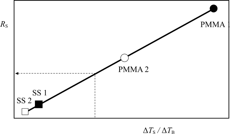 |
| Figure 2. Calibration line of ghf-01 (employing 2 SS, and 2 PMMA, samples of different thicknesses). |
Therefore, for an unknown sample, since F and Rint are known, by recording the three temperatures, we can obtain Rs and, thus, its thermal conductivity.
Further reading
Further information can be obtained in literature:
[1] ASTM E1530: “Test Method for Evaluating the Resisstance to Thermal Transmission of Thin Specimens of Materials by the Guarded Heat Flow Meter Technique”, American Society for Testing and Materials, 1916 Race Street, Philadelphia, PA 19103.